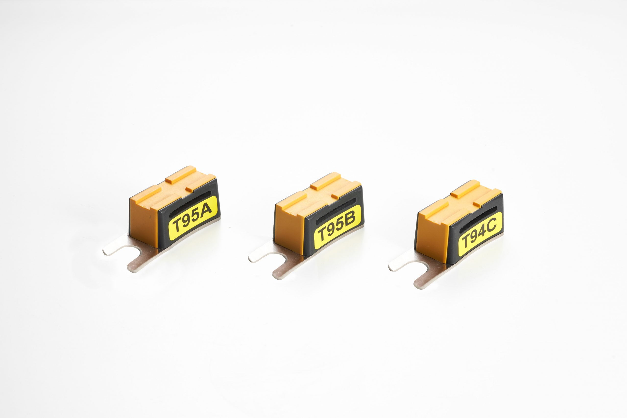


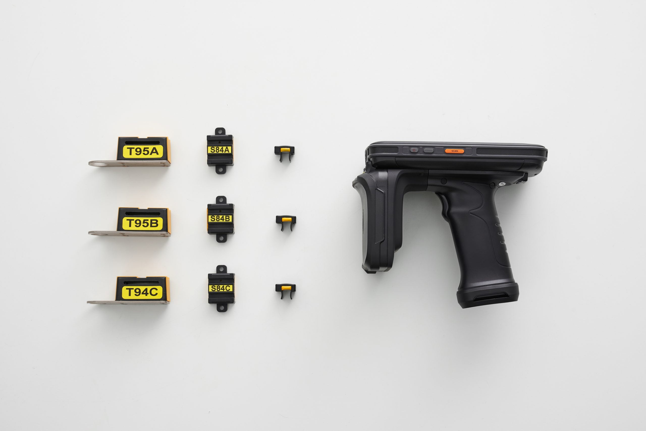


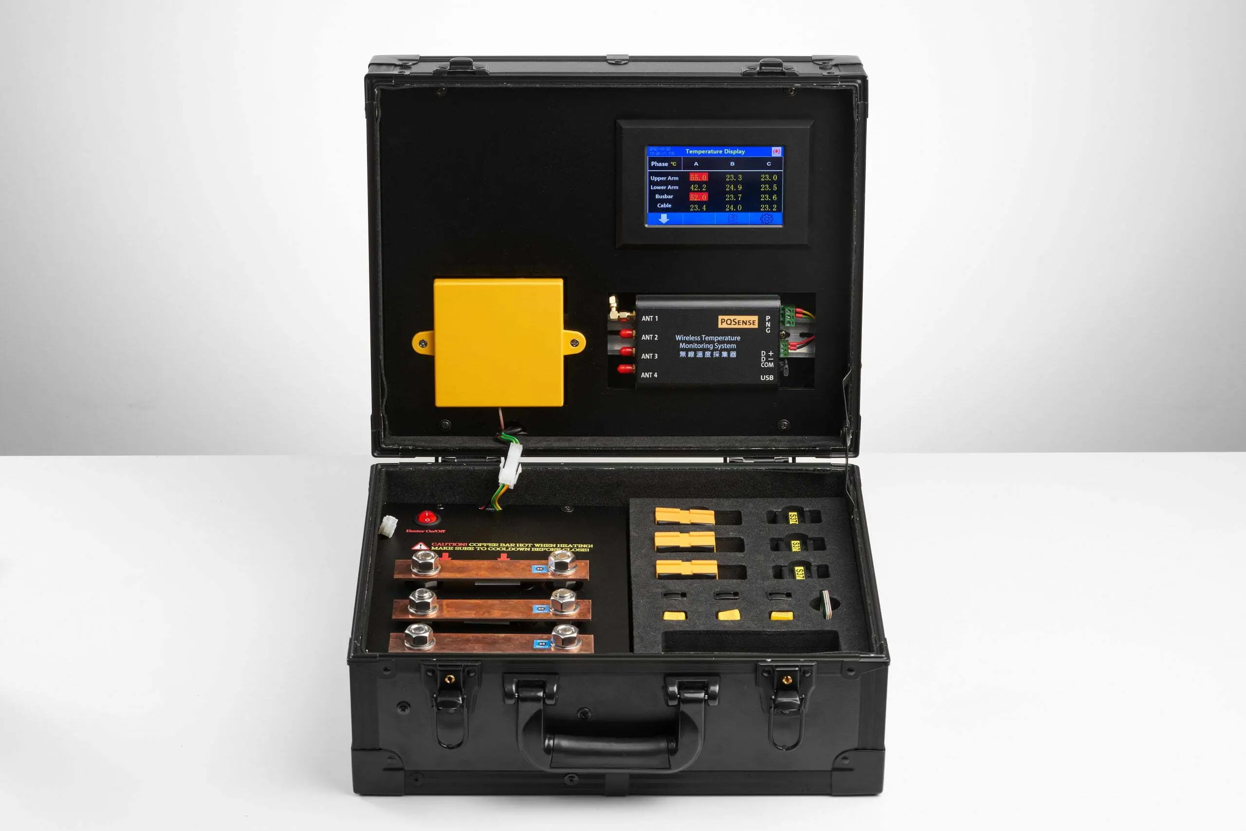


Start by assessing medium-voltage switchgear and low-voltage distribution panels supplying critical processes or facility equipment. Prioritize them according to the impact of a power interruption and available redundancy, then select the connections inside each cabinet. Passive RFID sensors must be installed during a power outage. After power is restored, a fixed system can collect temperatures continuously, or personnel can take readings with a handheld inspection system. When an alert occurs, the responsible person checks the measurement point, time, and operating conditions, arranges an on-site inspection, and records the action taken and post-maintenance follow-up.
Which power distribution equipment and connections should semiconductor fabs monitor first?
First inventory the medium-voltage switchgear and low-voltage distribution panels supplying critical tools and shared facility equipment, such as vacuum pumps and air compressors. Identify the loads served and the service coverage. If shared facility equipment serves multiple process areas, the effects of an outage may extend across those areas. Prioritization should also consider available redundancy, restart requirements, and previous abnormal-condition records.
- Panels supplying critical tools: Match panel identifiers to tool names, outgoing circuits, and phases so that an abnormal reading can be traced to the relevant tool, rather than simply recorded as “an overheating panel.”
- Panels supplying shared facility equipment: Record the areas served by vacuum pumps and air compressors, together with their primary/standby arrangements. Check whether backup equipment also depends on the same upstream supply section.
Once the cabinets have been selected, assess measurement points such as cable terminals, circuit breaker contacts, and busbar joints. Check cabinet space, insulation, and installation conditions, and ensure each point name identifies its actual location. For measurement-point priorities and configuration principles, see Electrical Hotspots and Measurement-Point Planning.
How should fixed and handheld monitoring be matched to different cabinets?
Choose a monitoring approach according to equipment criticality, the periods for which data is needed, and abnormal-condition alert requirements.
- Fixed monitoring: For critical facility supply panels that operate continuously for long periods and require visibility at night or between inspections, antennas and a fixed temperature reader continuously read the installed RFID sensors. Trends and abnormal-temperature alerts are available according to the configuration.
- Handheld inspection: Numerous, dispersed, lower-priority cabinets can be included in an inspection route where the inspection frequency meets the need. Personnel scan the installed sensors within their effective reading range, verify the measurement points, and retain the readings from that visit.
Data viewing can also begin with local instruments. The PQSense temperature monitoring system can operate independently without relying on the cloud. Any later connection to other monitoring systems or the cloud can be evaluated according to the fab’s requirements.
After an alert, how should responsibilities and the timing of action be coordinated?
After an alert, first verify the panel identifier, connection, time, and load at that time. Then determine whether a single tool or a shared facility system is affected. Temperature provides a lead for investigation; the cause still requires on-site inspection. The following responsibilities can be incorporated into existing abnormal-condition response procedures:
- Facilities: Confirm the supply coverage, redundancy, and condition of the distribution equipment, and coordinate inspection, isolation, and re-energization in accordance with safety procedures.
- Equipment engineering: Compare tool start/stop events, load, and equipment condition to help assess the effect on tool operation and the conditions required for return to service.
- Production: Identify affected batches and process schedules, and coordinate shutdown and production restart windows for the necessary action.
Qualified personnel should determine when to act according to site risks and safety procedures. Conditions requiring emergency action must be addressed immediately. For non-emergency conditions assessed as suitable for continued operation, observation can be intensified while work is scheduled for an annual shutdown or tool preventive-maintenance (PM) window. Timing should take temperature trends, load, and site risks into account rather than relying on a single temperature threshold.
After maintenance, recheck the same connection under similar load and operating conditions. Compare the readings with the work performed to confirm whether the improvement is sustained.
Maintenance records should retain, at minimum: the measurement point and time, operating conditions, the person taking over and inspection findings, the action taken, and subsequent recheck results.
Installation timing and acceptance checks
Sensor installation can be included in the outage window for an annual shutdown or scheduled yearly maintenance. Facilities and production should first confirm the affected tools, shared facility services, and power-restoration arrangements. Installation must take place only after power has been isolated and safety checks completed. Retain three checks at handover:
- Verify measurement points and functions. Confirm that sensor IDs, equipment names, and physical locations match. Check data updates, historical records, and alert functions according to the configuration.
- Confirm personnel handover. Make sure users know where to find an abnormal measurement point, who takes responsibility, and how to record outstanding work.
- Build an operating baseline. Some functional tests can be completed before re-energization. Once operation resumes, record temperatures at different loads and operating periods for later comparison.
After replacing a circuit breaker or changing the loads served, recheck the affected measurement points and records.
For an overview of monitoring priorities across semiconductor fab power distribution equipment, see “Which Power Distribution Equipment and Hotspots Should Data Centers and Semiconductor Fabs Monitor? A Complete Temperature Monitoring Guide” .
Planning a PQSense Wireless Temperature Monitoring Solution
PQSense can help assess cabinets, measurement points, and monitoring approaches on site, and plan the configuration around scheduled outages. The table below summarizes a fixed configuration. Battery-free sensors reduce the work of replacing sensor batteries:
In the semiconductor industry, a major assembly and testing plant in Taiwan has adopted PQSense as standard equipment throughout the plant, with more than 1,300 systems deployed. Wafer foundries and memory manufacturers have also adopted the system.
| Item | Specification |
|---|---|
| System components | Battery-free RFID temperature sensors, temperature-monitoring antennas, and a fixed temperature reader. |
| Power supply | The sensors are battery-free; the fixed reader requires an external power supply. |
| Suitable measurement points | Suitable copper busbar joints, circuit breaker contacts, or cable connections, depending on the sensor model. |
| Data interface | The fixed reader supports RS485 / Modbus RTU. Connection to the existing platform and responsibility for alerts must be confirmed during deployment. |
| Sensor measurement range and accuracy | Sensor models with published specifications: −20 to 125°C; accuracy ±2°C. |
| Deployment track record | According to PQSense’s October 2026 deployment reference, more than 16,000 systems have been deployed across more than 300 sites in 17 countries since 2017. About PQSense |
Contact us to discuss measurement locations and routine maintenance needs.
Further reading: How Can Semiconductor Fabs Reduce Unplanned Downtime Caused by Overheating Power Distribution Equipment? Learn more about assessing supply impact, redundancy, and maintenance timing.
FAQ
Can the same alarm temperature be set for different connections?
The same value should not be applied indiscriminately. Alert settings need to consider permissible equipment operating conditions, conductor and insulation materials, load, and historical temperatures. Even for the same type of equipment, confirm the actual conditions of use before the relevant personnel jointly determine the thresholds.
If a tool already has temperature monitoring, does its supply panel still need monitoring?
First check what the existing system measures. Process chambers, cooling systems, or the tool itself are different measurement targets from cable terminals, circuit breaker contacts, and busbar joints in the upstream supply panel. If the existing system does not cover those supply connections, tool temperature cannot be used to assess their condition.
Does a temperature drop after corrective action mean the problem has been resolved?
Not necessarily. Lower load or a tool shutdown can also cool a connection. First establish how the decrease relates to the action taken, then recheck under similar load and operating conditions. Retain inspection findings and work records; recurring temperature rises still require further investigation.
Further technical resources and videos
- The continuous thermal monitoring guide published by the Institute of Electrical and Electronics Engineers (IEEE) covers continuous thermal monitoring of switchgear and motor control centers up to and including 52 kV.
- PQSense RFID Temperature Monitoring: A Solution for Electrical Equipment Protection
- Smart Industrial Temperature Inspections: The PQSense Battery-Free RFID Handheld Solution