





AI Data Center
AI 資料中心如何規劃配電溫度監測?設備範圍與設計重點
高功率機櫃需要重新確認各供電迴路的設計電流、容量與備援安排。了解 AI 資料中心的配電分層、要先選哪些設備納入溫度監測,以及測點、天線與驗收條件在設計階段要確認什麼。


Temperature monitoring measures temperatures at specified locations continuously or periodically to help staff understand process, environmental and equipment conditions. It can verify process conditions, maintain suitable storage and operating environments, or help identify localized equipment heating early and plan inspection and maintenance.
Different monitoring purposes require different measurement locations, data frequencies and ways of interpreting the results:
| Monitoring purpose | Example measurement targets | What decisions does the data support? |
|---|---|---|
| Process monitoring | Furnaces, process vessels or materials being processed | Determine whether process conditions meet requirements and support adjustments by control systems or operators |
| Environmental monitoring | Air in factories, equipment rooms or storage areas | Determine whether the environment meets equipment operating or storage requirements |
| Equipment condition monitoring | Electrical connections, cable terminals and circuit breaker contacts | Identify localized temperature anomalies and plan inspection and maintenance |
Distinguish process, environmental and equipment monitoring objectives before choosing measurement locations and data collection methods.
Compare measurement methods by range, accuracy, installation conditions and data frequency.
Connect temperature records with investigation, maintenance and verification to make monitoring useful.
Reading guide: jump to the section that answers your question
What is temperature monitoring, and why does it matter?
Why does industrial equipment develop abnormal heat?
Where should you measure to obtain useful data?
Types of temperature monitoring systems
How do you choose between handheld inspection and fixed monitoring?
How do you select a suitable temperature monitoring system?
Equipment Condition Monitoring: Which Temperature Changes Warrant Inspection?
Equipment condition monitoring: how does it fit routine maintenance?
Find your next step by industry
The PQSense wireless temperature monitoring solution
Common leads in abnormal industrial equipment heating include deteriorating electrical connections, changes in load or cooling conditions, and mechanical friction. Record hotspot locations together with operating conditions to narrow the investigation.
Electrical connections: loose or corroded connections may increase contact resistance and cause localized heating at cable terminals, busbar joints or circuit breaker connections. Compare the load and inspect the actual connection condition.
Load and cooling: increased equipment load, obstructed ventilation or changed cooling conditions can raise temperatures. Compare current, ambient temperature and cooling equipment status.
Mechanical friction: inadequate bearing lubrication or abnormal operation may generate heat. Investigate the cause using vibration, lubrication and mechanical inspections together.
For power distribution equipment, continue your review with five categories of electrical connection hotspots and inspection priorities.

Match the measurement location to the question. Environmental monitoring measures air temperature in a space; equipment inspections must distinguish enclosure surfaces from internal connections. For power distribution equipment, first select important equipment based on the loads it supplies and the impact of an abnormality, then identify measurement locations inside it. The table below gives examples for general industrial equipment.
For example, to track a bolted busbar joint, confirm that the measurement covers that joint. To track a circuit breaker connection, distinguish the incoming side, outgoing side or actual contact. Map the panel number, circuit, side and phase to each measurement point so staff can locate the connection that needs inspection.
| Equipment | Connection / measurement location | Common risks or inspection focus | Suggested data collection method |
|---|---|---|---|
| Distribution panels / switchgear | Incoming and outgoing cable terminals; circuit breaker connections | Localized heating caused by looseness, corrosion or connection deterioration | Use thermography at observable locations; assess pre-installed sensors for specified concealed connections |
| Busbars / bus systems | Bolted joints and suitable tap-off connections | Joint deterioration or localized heating after increased load | Compare temperature, phase and load at each joint; assess fixed acquisition for important locations |
| Motor control centers (MCCs) | Cable terminals, contactors and suitable fuse connections | Hot connections that may affect power to pumps or fans | Record connection temperature together with equipment operation and circuit current |
| Transformers | External bushings, terminals and cable connections suitable for measurement | Hot external connections; inspect internal windings using the manufacturer's methods | Assess thermography or suitable sensors for external bushings and terminals; winding temperatures require a separate suitable solution |
| Motors / pumps | Specified locations such as housings and bearing housings | Abnormal load, cooling, lubrication or friction | Use consistent measurement locations and combine temperature, vibration and lubrication inspections |
Thermocouples, RTDs and thermistors are sensing elements; wired and wireless describe how data is collected. Selection should consider measurement range, accuracy and acquisition configuration together. NI temperature sensor guide
The table compares common industrial temperature measurement methods. Ranges are approximate or specific to individual equipment and support initial screening; measurement range and the ambient temperature an instrument can withstand are different specifications.
| Common method | Measurement target | Data collection | Reading and installation conditions | Maintenance focus | Measurement / applicable temperature range |
|---|---|---|---|---|---|
| Wired sensors: thermocouples, RTDs and thermistors | The location or medium in contact with the probe | Wired to an instrument or acquisition device; continuous recording depends on configuration | Probe contact, wiring and electrical isolation must suit the equipment | Check probes, connections and measurement accuracy | Thermocouples: approx. −210 to 1760°C; RTDs: approx. −240 to 650°C; thermistors: approx. −40 to 250°C |
| Infrared thermometer | Surface temperature of the target area | Staff aim the instrument to obtain a reading at that time | Requires a suitable viewing path; distance and measurement area affect the reading | Check the lens, power supply and measurement settings | Approx. −30 to 500°C |
| Thermal imaging camera | Surface heat distribution within the field of view | Handheld inspections capture thermal images; fixed configurations can observe continuously | Requires a suitable viewing path, with emissivity and reflections considered | Check optics, settings and image records | Approx. −20 to 550°C (in separate ranges) |
| Battery-powered wireless sensors | Locations where sensors are installed | Battery-powered sampling and transmission to a receiver according to settings | Confirm sensor mounting, wireless coverage and access for battery maintenance | Track battery condition, transmission and data completeness | Approx. −40 to 125°C (probe) |
| Passive RFID temperature sensors | Connections or locations with installed sensors | Powered and read by RF; used with handheld inspection or fixed acquisition | No direct view of the sensor is required; plan effective reading coverage and antenna placement | Sensors need no battery replacement; installation, reading equipment and data still require checks | Approx. −20 to 125°C |
| Fiber-optic temperature measurement (point probes) | Locations of fiber-optic probes, such as suitable windings or specified hotspots | Probes connect to dedicated acquisition equipment for continuous point data | Assess electrical isolation, probe mounting, fiber routing and bend radius | Check probes, connectors, fiber integrity and channel mapping | Approx. −200 to 300°C (acquisition equipment range) |
These ranges are an overview and vary by model, sensing element and packaging; they are not universal limits for each technology. Probe measurement range is not the acquisition unit's allowable ambient temperature. For fiber optics, verify the probe, calibration and continuous versus short-duration operating conditions.
An infrared thermometer measures the surface temperature of a target area; a thermal imaging camera shows surface heat distribution within its field of view. Both require consideration of emissivity and other measurement conditions. Infrared temperature measurement and thermography applications
To distinguish observable surfaces, sensor locations and inspection time coverage, read how manual inspection, thermography and continuous temperature monitoring work together.
For periodic checks, staff can visit the equipment to obtain readings at that time. To capture changes between inspections, assess fixed continuous acquisition. With RFID, a handheld inspection system reads multiple installed sensors; a fixed configuration collects point temperatures continuously according to its settings and can provide historical records and alerts.
For example, daytime inspection readings may be normal while equipment operates intensively during the night shift. Fixed monitoring can fill that gap in the temperature record and help compare changes across periods.
See the assessment criteria and configuration guidance for continuous monitoring, and the wireless temperature monitoring system selection guide.
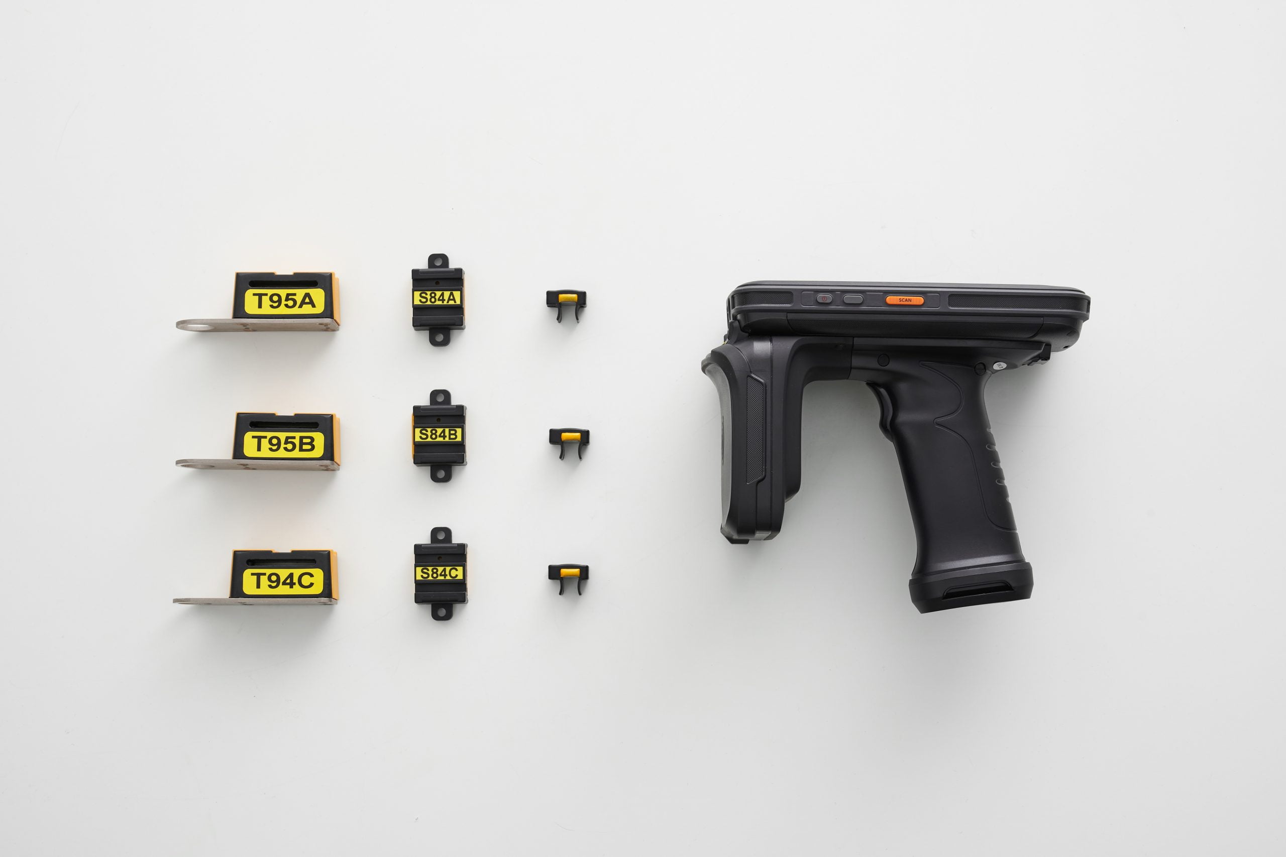
Handheld inspection demonstration: scan multiple installed points in one pass and match point names with readings recorded during the visit.
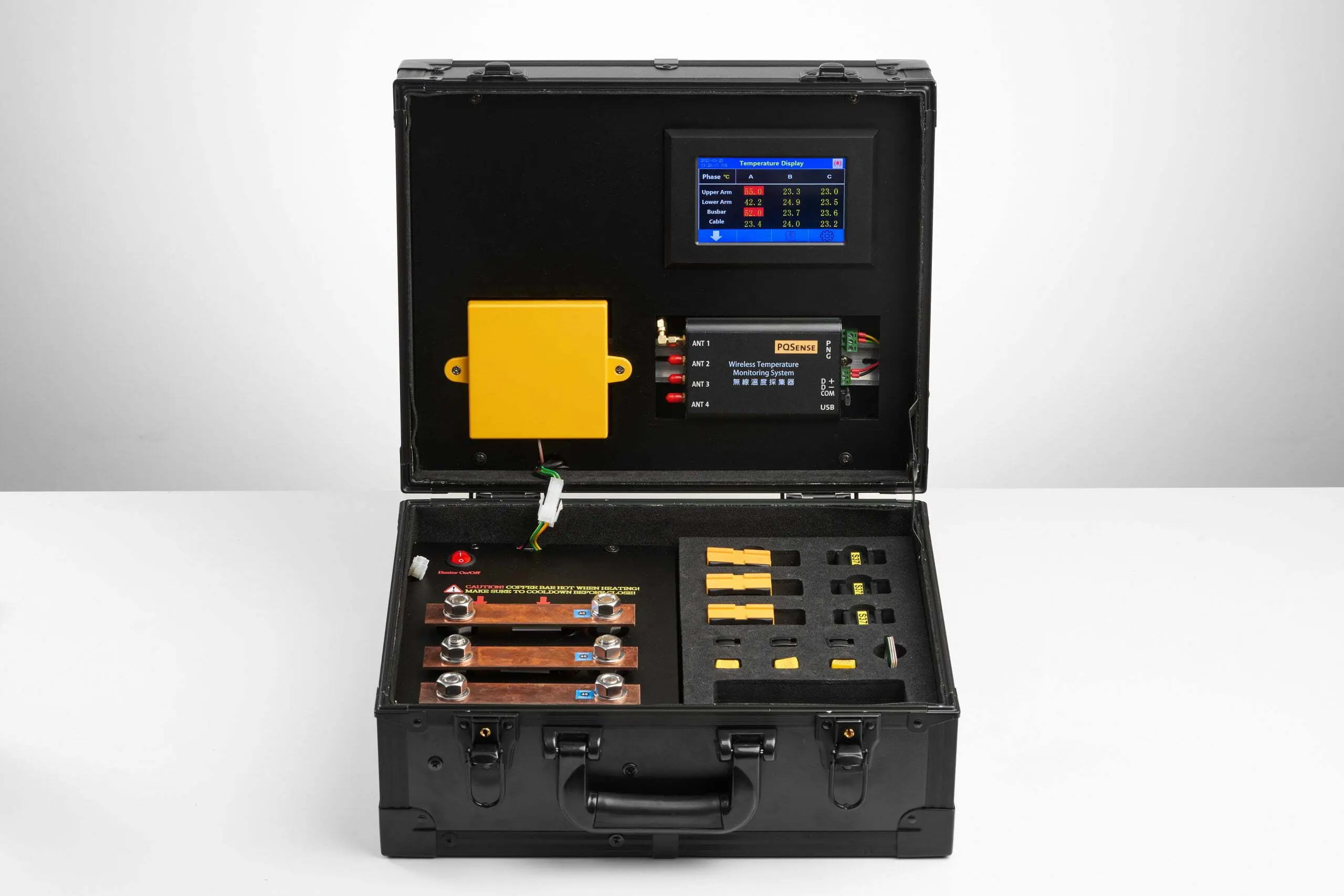
Fixed monitoring demonstration: from sensors at connections inside the panel and antennas to acquisition equipment and a local display.
First identify the measurement target and how the data will be used, then compare range, accuracy, installation and data collection requirements. Use the following information when discussing procurement with a supplier:
Measurement target: identify whether you need environmental, process or equipment connection temperatures, and whether the temperature at that location can be obtained on site.
Monitoring frequency: handheld tools can support periodic checks; assess fixed continuous acquisition when you need to capture changes between inspections.
Range and accuracy: provide expected operating temperatures, anomaly assessment needs and sensor locations to confirm measurement capability.
Real-time alerts: identify who receives notifications and how subsequent inspection and corrective action will be handled.
Integration: identify the existing system that will receive the data, its interfaces and measurement-point naming conventions.
Remote access: if remote viewing is needed, confirm the network, platform and data-access configuration.
Installation and maintenance: assess measurement points, wiring or wireless reading conditions, power and ongoing maintenance together.
Start by comparing the same connection under similar load and environmental conditions. For other equipment, also use consistent measurement locations and check operating conditions. The electrical connection and motor examples below show changes worth investigating; the actual cause still requires an on-site inspection.
Compare load and environmental conditions first. If it remains hotter under similar loads, prioritize that connection for inspection and review recent installation, wiring or equipment changes.
Check for increased load or changes in ventilation or cooling. If one point stands out, focus on that connection. Retain the location and phase of each point when comparing readings.
Confirm whether the measurement is from the motor housing, bearing housing or another location, then combine load, vibration and lubrication checks. Normal temperatures at different locations cannot be compared directly.
Cooling while equipment is stopped does not demonstrate a successful repair. Recheck the original point under comparable operating conditions and retain the corrective work and before-and-after records.
Alarm thresholds should consider equipment limits, measurement location and normal loaded-operation records. IEEE Std 2969-2025 provides continuous temperature monitoring guidance for applicable switchgear and motor control centers; different locations may have different normal temperatures.
Before deployment: list measurement locations, existing data gaps, and installation and maintenance windows. Sensors at electrical connections must be installed during an outage. After re-energization, verify readings and establish temperature records under representative operating conditions.
At handover: verify point names, physical locations and data completeness, and confirm abnormality notifications and responsible staff. For electrical equipment installation and acceptance, see the power distribution temperature monitoring deployment guide.
During shift reviews: confirm that data continues to update, take ownership of new alerts, and check the corresponding equipment and operating status.
During periodic reviews: identify recurring hot points, reading interruptions or significant changes after load adjustments, and arrange inspections and supplementary measurements.
After maintenance or changes: recheck under comparable loaded conditions; update the point register when equipment is expanded or circuits change.
For each response, record at least the measurement point, event time, load, inspection findings, corrective action and verification result. Set the review frequency according to equipment importance, manufacturer requirements and site procedures.
Semiconductor fabs can first assess panels supplying critical tools or shared facility equipment; see the guide to semiconductor electrical overheating and downtime risk. Data centers can start with panels supplying important customer racks or critical computing services, then confirm monitoring locations such as busbar joints and circuit breaker contacts inside those panels.
To identify priority power distribution equipment by industry, continue with “Which Power Distribution Equipment and Hotspots Should Data Centers and Semiconductor Fabs Monitor? A Complete Temperature Monitoring Guide” .
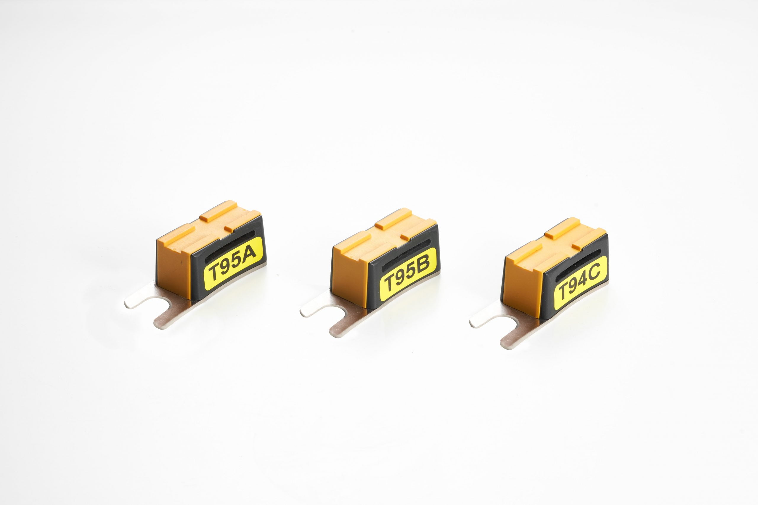
The PQSense wireless temperature monitoring solution uses battery-free passive RFID temperature sensors at electrical connections, paired with a handheld inspection system or fixed acquisition equipment to help maintenance staff track localized temperature changes.
Since 2017, PQSense has deployed more than 16,000 systems in 17 countries, including more than 5,600 in Taiwan, according to its October 2026 deployment reference. About PQSense
Handheld inspection: scan multiple installed sensors within the effective reading range, using point identification and records to reduce individual aiming and manual transcription.
Fixed monitoring: antennas and readers continuously acquire connection temperatures, filling information gaps between inspections.
| Item | Specification |
|---|---|
| System components | Battery-free RFID temperature sensors, temperature monitoring antennas and fixed temperature readers. |
| Power supply | The sensors are battery-free; the fixed reader requires external power. |
| Suitable measurement points | Suitable busbar joints, circuit breaker contacts or cable connections, depending on sensor model. |
| Data interface | The fixed reader supports RS485 / Modbus RTU. Connections to existing platforms and responsibility for alerts must be confirmed during deployment. |
| Sensor measurement range and accuracy | Sensor models with listed specifications: −20 to 125°C; accuracy ±2°C. |
| Deployment track record | According to PQSense’s October 2026 deployment reference, more than 16,000 systems have been deployed across more than 300 sites in 17 countries since 2017. About PQSense |
Select electrical connection sensors to suit the equipment structure and verify reading with doors normally closed and covers in place. Refer to sensor products and installation examples to confirm suitable busbar joints, contacts, cable joints, transformer bushings and terminals.
Contact PQSense to discuss a temperature monitoring solution suited to your equipment and inspection needs.
Industries that need to track the temperature of critical electrical equipment can assess monitoring according to the equipment and measurement-point conditions. PQSense’s deployment reference lists petrochemicals, semiconductors, steel, wire and cable, utilities, electronics manufacturing, data centers, energy storage systems, and renewable energy plants. Temperature monitoring for general processes and storage environments can also be planned around operating and preservation requirements; suitable measurement methods and solutions need to be assessed separately.
Yes, with acquisition equipment, networks and platforms that support remote access. If data is mainly viewed on site, a local display configuration is also an option.
Wireless systems measure temperature using sensors and transmit data wirelessly to reading equipment. Passive RFID temperature sensors are powered and read by RF; the handheld or fixed acquisition configuration determines when data is collected.
No. The enclosure surface and internal connection are different measurement locations. To investigate a specific joint, confirm whether the observable surface or installed sensor covers that location.
Keep temperature records for the same location under similar operating and environmental conditions. Track persistent heating or recurring anomalies, and connect the findings with inspection, corrective action and verification.

How can semiconductor fabs use passive RFID temperature monitoring for power distribution? Explore equipment selection, fixed and handheld configurations, cross-team alert handover, and PQSense installation during outages and acceptance checks to connect temperature data with routine maintenance.

Discover how PQSense’s Passive Wireless Temperature Monitoring System delivers real-time, battery-free monitoring for switchgear, substations, and critical power systems—reducing risk and eliminating maintenance.

Discover how Smart Home Insurance providers can prevent electrical fires with PQSense’s real-time monitoring sensors. Proactive protection saves costs, reduces risk, and builds customer trust.

Discover the PQSense handheld temperature monitoring system—powered by RFID, battery-free, and designed for fast, accurate industrial inspections. Replace infrared guns with smarter, real-time scanning.