










Process tools and facility systems in semiconductor fabs depend on a stable power supply. Persistent heating caused by deteriorating electrical connections can affect equipment operation and lead to unplanned downtime. Tracking connection temperatures helps identify abnormalities earlier so inspections can be arranged. Start with cable terminals, busbar joints and circuit breaker connections supplying important equipment, then prioritize coverage according to the impact of a supply interruption and the information available from existing inspections.
How should monitoring points be configured across a fab's power distribution system?
A semiconductor fab can plan monitoring points across main distribution panels, panels supplying process tools, and circuits serving cooling, vacuum and exhaust equipment. Sensors and readers are configured according to the enclosure layout and monitoring needs.
Cable terminals, busbar joints and circuit breaker connections are worth considering when planning temperature monitoring. They are also among the locations identified in the continuous thermal monitoring guide published by the Institute of Electrical and Electronics Engineers (IEEE). Actual monitoring points should reflect equipment layout, supply functions and site installation conditions. The table below outlines configuration considerations for common supply locations in semiconductor fabs.
| Equipment or supply location | Sensor monitoring points | Configuration considerations |
|---|---|---|
| Medium-voltage switchgear | Incoming and outgoing cable terminals, busbar joints and suitable circuit breaker main-circuit contacts | Plan antenna coverage around compartments and metal partitions; sensor placement and mounting must respect insulation requirements and operating clearances |
| Connections between transformers and distribution equipment | External cable terminals or busbar connections on the high- and low-voltage sides | Identify the side and phase, and arrange reading around terminal locations; distinguish external connection readings from internal temperatures such as winding temperatures |
| Main low-voltage distribution panels | Incoming terminals, main busbar joints, branch connections and circuit breaker terminals | Position sensors and arrange reading around closely spaced conductors and covers; distinguish shared busbar data from individual branch data |
| Panels supplying process tools and facility equipment | Important outgoing cable terminals, circuit breaker line- and load-side terminals, and suitable fuse clips | Map point names to downstream tools, pumps or other support equipment; select fixed or handheld reading according to inspection and continuous tracking needs |
| Capacitor and power factor correction circuits | Cable terminals, switch contacts and suitable fuse clips | Select accessible monitoring locations for the equipment configuration and identify each group of connections; record enclosure and connection temperatures separately |
Process tool supplies: map each reading to the tool and the actual connection. A panel may supply several tools, so point names should identify the outgoing circuit, tool function, connection location and phase. For example, a sensor on the load-side terminal of a tool's supply breaker represents that location; it does not substitute for readings from the line side or other phases. This mapping narrows the search after an abnormality and supports comparison with tool operating periods.
Shared facility equipment supplies: select the reading approach according to service coverage and operating periods. Where cooling water pumps, vacuum or exhaust equipment serve multiple tools, fixed monitoring can be configured at their supply connections when continuous tracking is needed. It retains temperature changes when personnel are absent for comparison with equipment operating records. In other areas managed mainly through periodic inspections, handheld RFID can collect readings and records from multiple installed sensors during each visit.
How should monitoring points be prioritized when the budget is limited?
Start with connections where an interruption would have a greater impact, backup is limited or existing observations warrant follow-up. Then consider whether current inspections provide the information needed. This focuses the first phase on important locations. Voltage level, panel size or the highest current temperature should not determine priority on its own.
- Trace the supply path to establish the scope of impact. Work upstream from important process tools and cooling, vacuum or exhaust equipment to identify the panels, breakers and shared connections along the path. Check whether primary and backup equipment share an upstream supply. This helps avoid monitoring only near the tools while overlooking shared supply components.
- Review connections with changes worth tracking. Points with a history of temperature rises, recent maintenance or replaced connection components can be prioritized for assessment. Equipment already showing abnormalities still requires appropriate inspection; adding monitoring does not replace corrective action.
- Identify gaps in existing inspection information. Prioritize fixed monitoring for important connections requiring observation overnight, during load changes or between inspections. Select suitable reading arrangements for other areas as part of a phased deployment.
For example, two panels may have similar rated capacities, but one supplies auxiliary equipment that can alternate duties while the other supplies exhaust equipment shared by several tools. If alternative supply is limited for the latter, its important connections may deserve an operating baseline even without an obvious temperature rise. This is a planning decision based on supply impact, not evidence that the equipment is already faulty.
Once the first phase is defined, the point list should distinguish covered connections, deferred points and those not yet included. It provides a reference for maintenance and later expansion. Priorities among incoming feeders, bus ties and low-voltage outgoing circuits should reflect their actual supply functions and backup arrangements.
PQSense passive wireless RFID temperature monitoring solutions
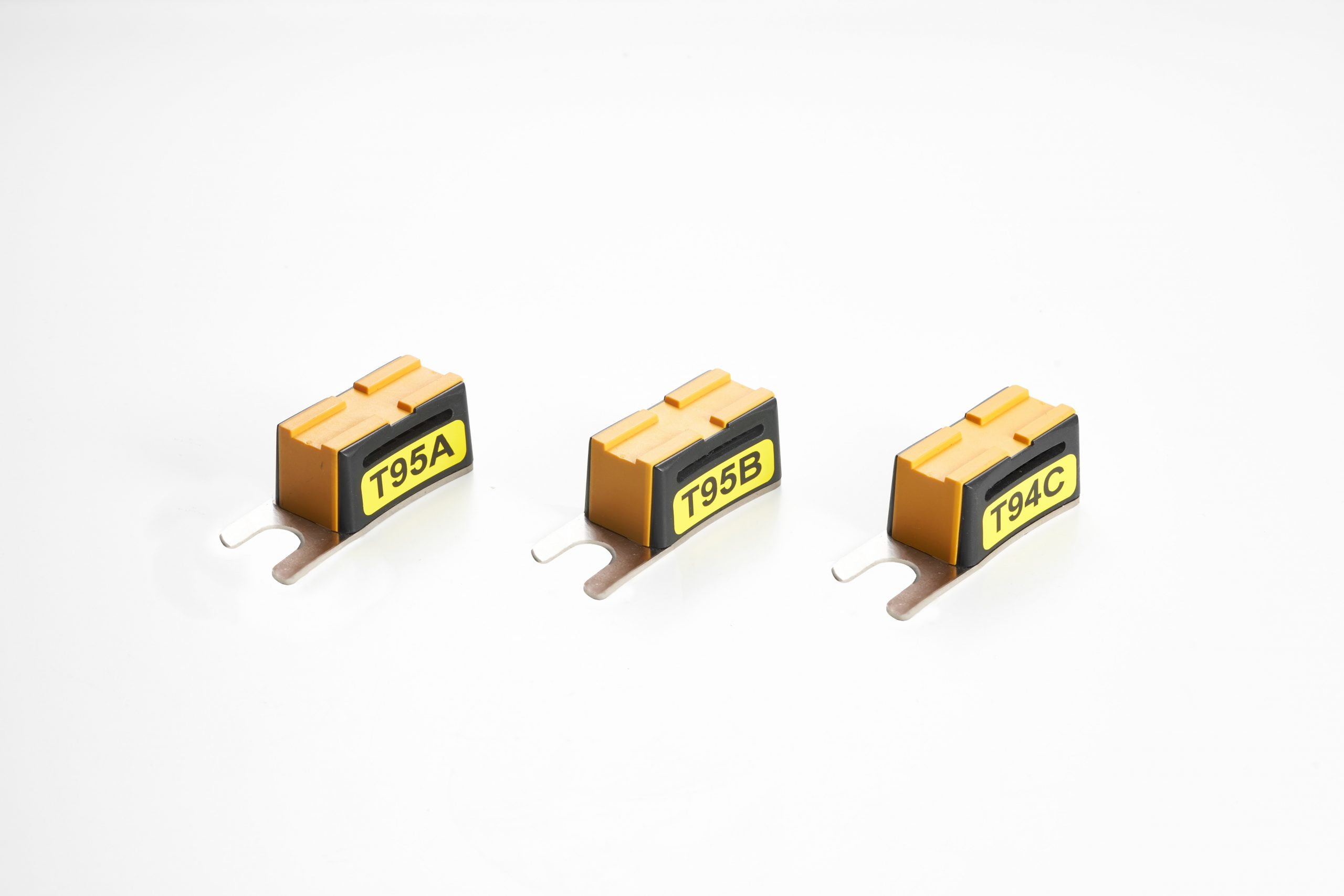
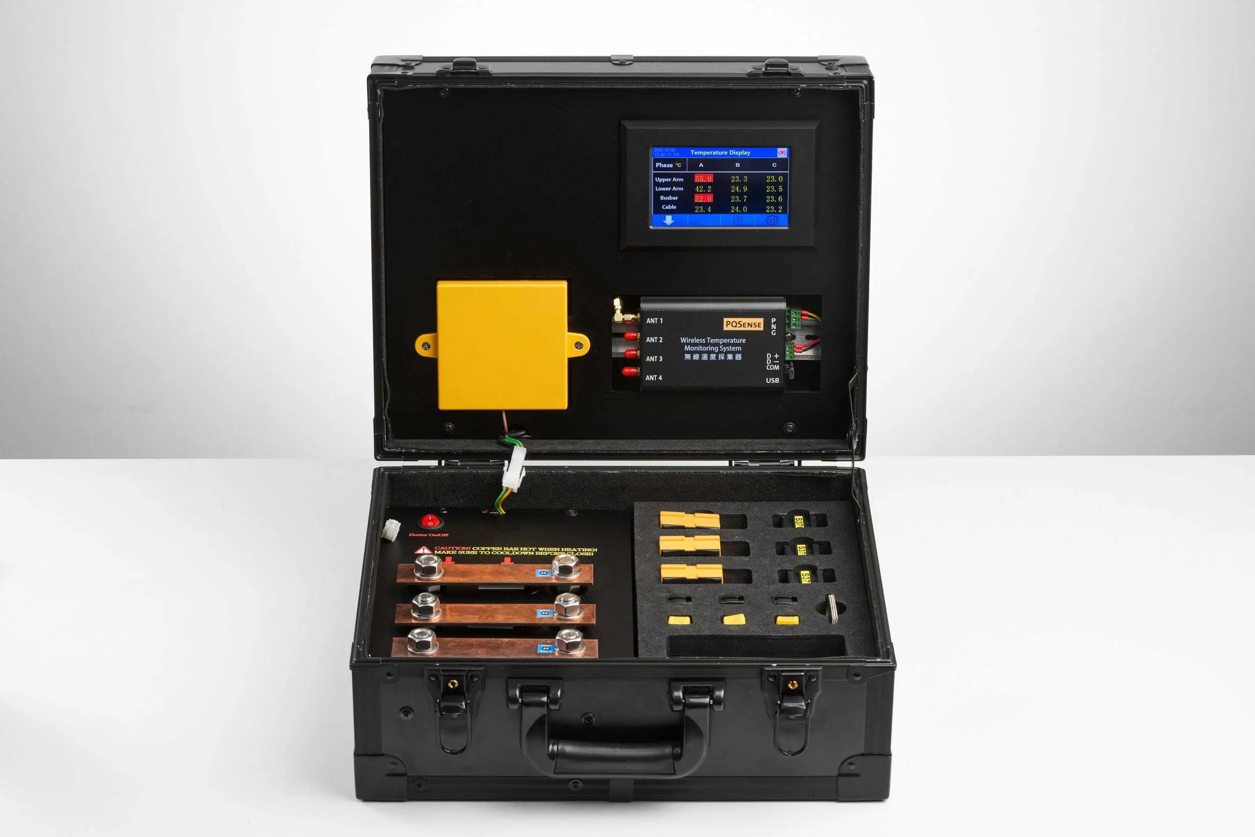
PQSense uses battery-free RFID temperature sensors with antennas and fixed or handheld temperature readers to collect temperatures at selected electrical connections. Battery-free sensors reduce battery replacement needs. Fixed configurations continuously track important points, while handheld systems support multiple-point reading and recording during inspections.
For semiconductor fabs, simply tell PQSense which equipment or connections you want to prioritize. The team can assess the site and help define suitable monitoring points and configurations. Assessment covers actual connection locations, reading conditions and intended data use so each point maps to equipment the maintenance team needs to track.
Contact us to discuss equipment priorities and monitoring point planning.
Further reading: How PQSense Works in Semiconductor Fabs: Monitoring the Electrical Backbone of Chip Manufacturing explores applications in medium- and low-voltage distribution.
FAQ
How many sensors should be installed in each panel?
The number depends on the connections and phases to be covered and the equipment layout. There is no fixed count suitable for every panel. Monitoring only important outgoing connections requires a different configuration from covering incoming connections, busbars and several branch circuits in the same panel.
Should new equipment without a history of overheating be included?
It can be included according to its impact on power supply. Monitoring new equipment establishes a baseline during normal operation for comparison when loads or connection conditions change. Priority should still reflect equipment function and inspection needs, rather than age alone.
Does a normal temperature on an unloaded backup circuit mean it is ready for service?
Temperature without load cannot establish backup readiness on its own. A connection may show no obvious rise when it carries no current, so existing backup tests and equipment inspections remain necessary. When records from load tests or actual transfers are available, evaluate temperatures together with those operating conditions.
Should the monitoring plan change when new tools are added?
Review the affected supply paths. New tools may change branch loads or add equipment to a shared supply section. Use these changes to assess whether more points or different continuous monitoring coverage are needed, and retain equipment and load records from before and after the change.