






Select equipment first, then confirm the configuration. Start with power distribution equipment supplying critical loads: panels serving rows of critical racks, upstream switchgear and transformers, and equipment supplying cooling pumps, fans and chillers. Configuration planning covers measurement-point locations, antennas and readers, cable routes and acceptance criteria.
Addressing these items together during design can reduce later modifications and construction coordination. Sensors are installed on connections that are energized during operation, so installation requires an outage. Planning early allows the work to be completed during construction or an existing outage window.
What Changes with High-Power Racks?
- Supply circuits and current loading: Higher rack power requires a review of each circuit's design current, capacity and redundancy. Actual current distribution depends on supply voltage, circuit count and redundancy architecture; it does not necessarily become concentrated in fewer upstream assets. However, connections carrying higher currents experience greater heating due to contact resistance.
- Load over time: AI training and batch workloads can draw substantially different amounts of power at different times. Rack additions are also phased, so the current carried by the same panel may change considerably between quarters. A single measurement is therefore less representative of actual equipment conditions.
Power Distribution Levels and Their Thermal Risks
| Distribution level | Role in the supply path | Main thermal risk locations | Decisions to make during planning |
|---|---|---|---|
| Medium- and low-voltage switchgear | Switching and protection between the utility supply and UPS | Incoming and outgoing cable terminals, busbar joints and bolts, breaker moving and fixed contacts | Loads supplied, redundancy architecture, provision for connection temperature sensing and observation |
| Transformers | Voltage conversion while carrying sustained loads | Bushings, external cable connections and terminals | Capacity margin, accessible terminal measurement locations, scope of the manufacturer's condition monitoring |
| UPS and transfer equipment | Uninterruptible supply and transfer between supply paths | Internal and external wiring terminals | Whether terminals can be measured; use manufacturer monitoring for internal components |
| Distribution panels, PDUs and RPPs | Distribution to rack groups or areas | Outgoing terminals, breaker connections and busbar joints | Racks supplied per panel, expansion allowances, number of measurement points |
| Busway | Supply along rack rows through tap-off units | Tap-off contacts and conductor joints | Ambient temperature and derating conditions, tap-off locations and future expansion points |
| Rack PDUs | Supply to IT equipment within racks | Internal breakers, connectors and outgoing connections | Maximum ambient temperature rating; some designs offer no derating flexibility, so manufacturer specifications must be checked |
Where Is Continuous Connection Temperature Data Needed?
Start with equipment supplying critical loads, rather than attempting to enumerate every connection or section of the supply path. Cooling equipment can lose power and affect heat removal even while servers remain powered, so its supply connections should also be reviewed.
Then consider three conditions:
- Accessibility. Closed panel doors and drawout structures can block the infrared view of connections. Whether doors may be opened for measurement depends on the site's safety assessment and procedures. Such locations are strong candidates for including sensors and antennas during design.
- Load variation. Large changes between operating periods or phased expansion make isolated measurements difficult to compare. Continuous data helps establish a baseline under similar loading.
- Backup paths. Review primary and backup paths separately. In some redundant architectures, a backup path carries little load and has normal temperatures until it takes a larger load after transfer. Its usual readings do not establish its condition after that transfer.
Items to Confirm Together During Design
- Measurement-point list and locations. Decide which assets and connections will receive sensors, then match sensor designs and installation methods to the connection type, such as busbars, breaker contacts or cable terminals.
- Antenna and reader configuration. Antenna positioning affects whether sensors can be read with doors closed. Readers require power and connecting cables, so their locations should be coordinated with panel design.
- Cable routes and panel space. Plan antenna-to-reader cables, entry openings and internal space during panel manufacture or modification.
- Division of work with power monitoring. Power monitoring tracks current, voltage and operating status; connection sensing measures temperatures at connections. Confirm where each data source provides coverage, then interpret readings alongside current, contact condition and heat dissipation.
- Installation window. Sensor installation requires an outage and completion of safety checks. Coordinate it with construction, sectional outages or annual maintenance.
- Expansion allowances. Equip the assets serving current critical loads first if appropriate, while reserving locations and routes for future sensors and antennas. Complete deployment in phases alongside construction and outage windows.
- Acceptance criteria. Verify that each sensor ID corresponds to the correct physical connection and test reading with panel doors in their normal closed position. Record initial readings and the load at the time as a baseline for later comparison.
For construction scheduling and outage planning at an existing site, see How to Introduce Power Distribution Temperature Monitoring in an Existing Factory.
PQSense Passive Wireless RFID Temperature Monitoring
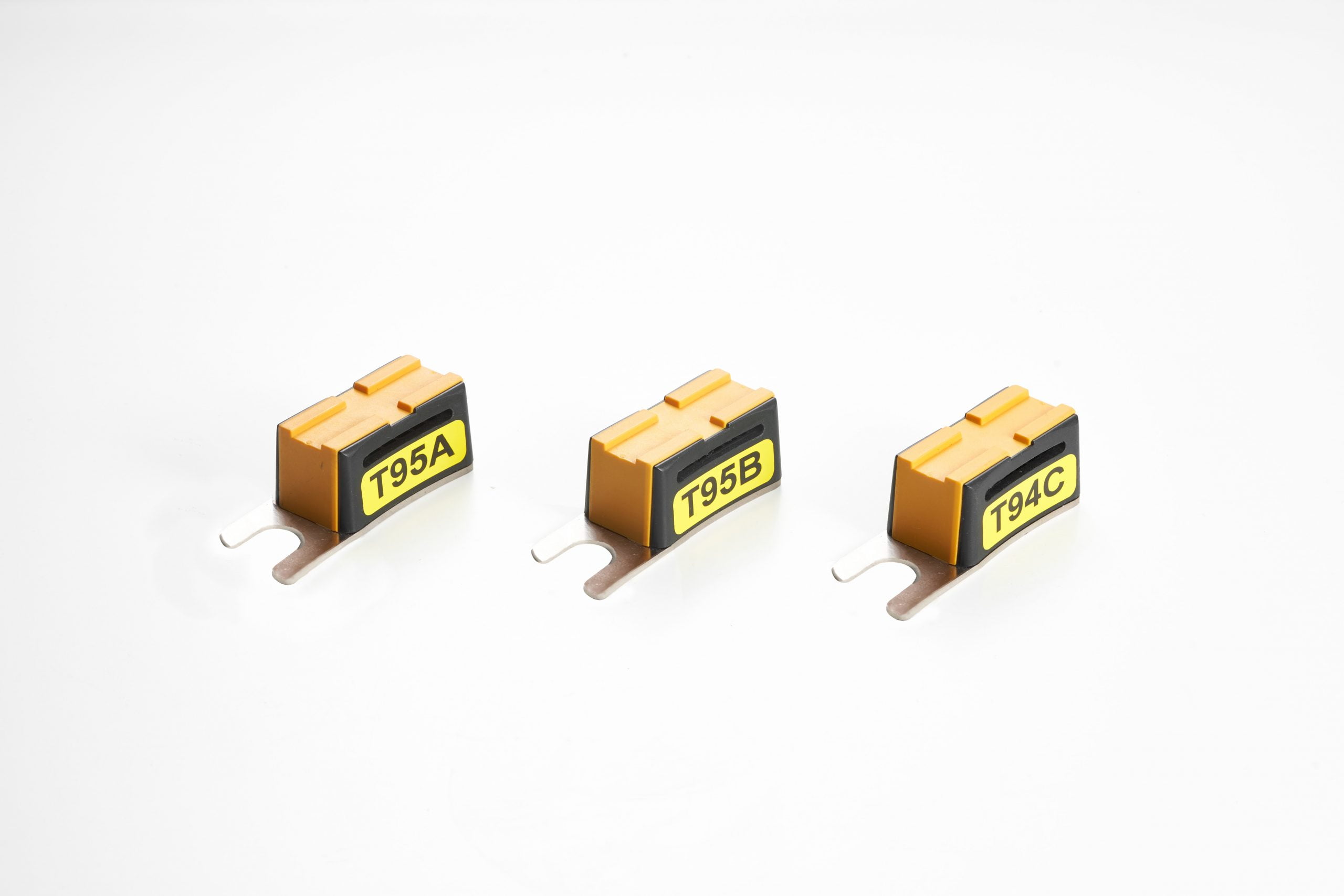
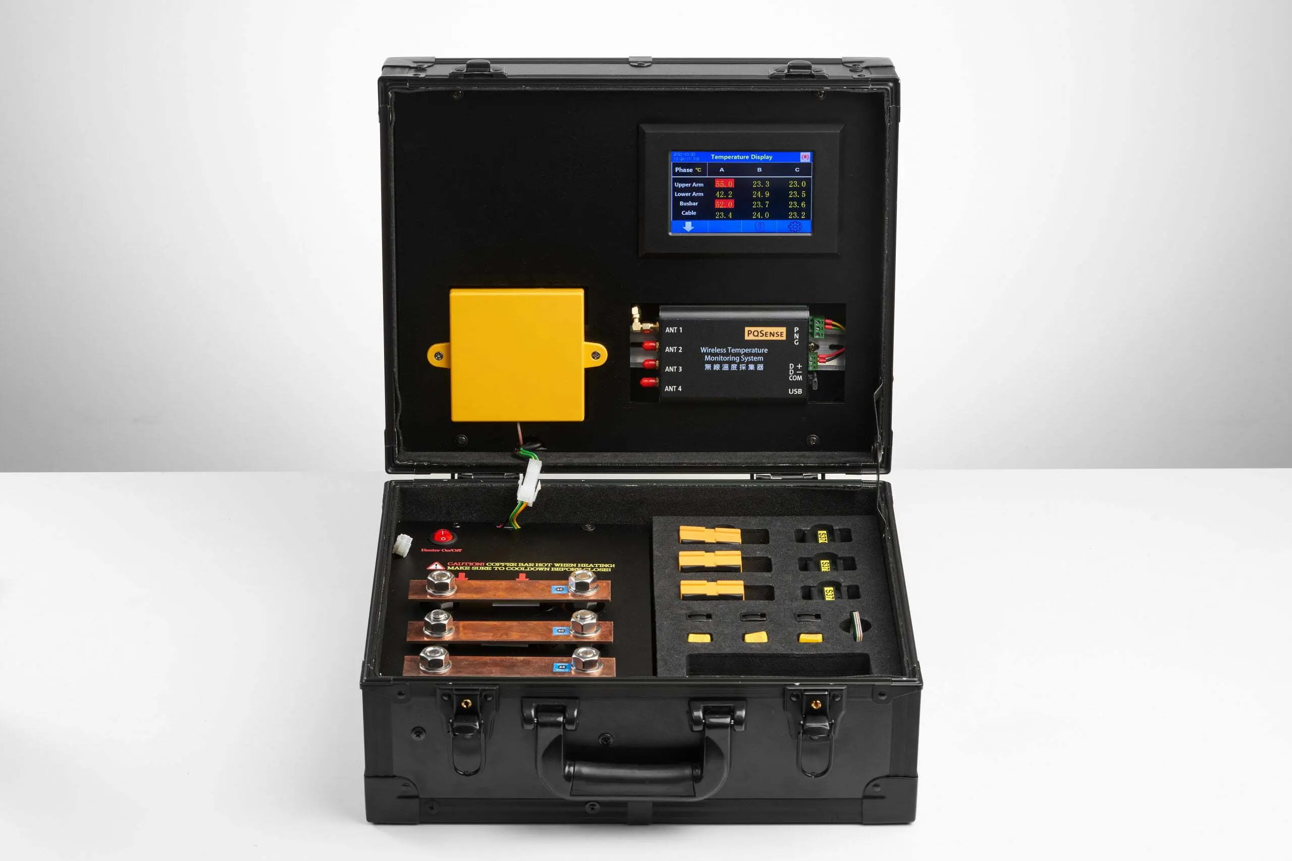
PQSense provides battery-free RFID temperature sensors, fixed temperature readers and handheld readers for monitoring specified locations in power distribution equipment. During measurement-point planning, first identify the connection type, then match the sensor design and installation method (see PQSense product information). Antennas connect to readers by cable, and readers require power; both must be included in panel and cable-route planning.
Contact us to discuss measurement points and antenna configurations for new construction or expansion.
FAQ
If a Rack PDU Already Provides Power and Temperature Data, Are Upstream Measurement Points Still Needed?
First check where the existing readings are taken. Air near a rack, components inside a PDU and terminals on an upstream panel are different measurement targets. Review their coverage individually to determine whether upstream connection data is still missing.
What Information Is Needed During Design to Plan Measurement Points?
Planning requires a list of critical equipment and the loads supplied, the locations and types of connections to be monitored, panel structure and internal space, and available construction and outage windows. These are planning inputs; the actual scope must be confirmed for each project.
Related Reading
- As AI Data Center Power Density Rises, How Should Electrical Connection Monitoring Keep Up?
- Which Data Center Power Distribution Equipment and Hotspots Should Be Monitored?
- Which Power Distribution Equipment and Hotspots Should Data Centers and Semiconductor Fabs Monitor? A Complete Temperature Monitoring Guide