






When planning power distribution temperature monitoring for a data center, first identify the racks, customer services, and cooling equipment whose power supply should be prioritized. Then identify the distribution panels, switchgear, and other equipment supplying those loads. Only after selecting the equipment should its structure be used to identify suitable monitoring locations, such as internal busbar joints, circuit breaker contacts, cable connections, or transformer bushings and terminals.
Equipment priority depends on the criticality of the loads served, the impact of a power interruption, and redundancy. This article covers equipment and measurement-point selection through to the checks needed for installation and acceptance.
How Should Power Distribution Equipment Be Prioritized for Monitoring?
For example, a distribution panel supplying a rack leased by an important customer may warrant priority monitoring even if it serves only that one rack. Establish the panel's importance first, then review suitable measurement points inside it and the monitoring data already available.
The site's single-line diagram and equipment layout help establish which loads are served and how redundancy is arranged. Sensors are installed at conductive joints within the equipment, such as internal busbar joints.
If cooling equipment supports heat removal for critical racks, its supply panels also warrant evaluation. This article focuses on suitable electrical connections within those panels. The cooling performance and mechanical condition of pumps, fans, or chillers must still be assessed using their respective monitoring data.
Common Data Center Power Distribution Equipment and Monitoring Locations
After selecting critical supply equipment, identify suitable cable terminals, busbar joints, and circuit breaker contacts inside it. For transformers, assess bushings and terminals according to the structure. The table below summarizes installation examples for common equipment.
When selecting equipment, first record the loads it supplies and the range of operating current (A). The loads listed below are planning examples and should be confirmed against the site's single-line diagram.
| Equipment type | Suitable locations in or on the equipment | Typical loads served |
|---|---|---|
| Medium-voltage switchgear | Internal cable terminals, busbar joints, and circuit breaker contacts | Downstream transformers and critical distribution areas |
| Transformers | Bushings and wiring terminals, as appropriate to the structure | Low-voltage distribution panels and the IT and cooling loads they supply |
| Ring main units | Suitable high-voltage switches, cable terminations, and busbar locations inside the enclosure | Medium-voltage feeders and connected transformers |
| Low-voltage distribution panels | Suitable internal busbar joints and cable connections | Critical racks, customer services, and auxiliary equipment |
| Cooling equipment supply panels (including motor control centers) | Suitable busbar joints and cable connections inside the supply panel | Cooling equipment such as pumps, fans, or chillers |
Which PQSense Sensors Suit Different Electrical Connections?
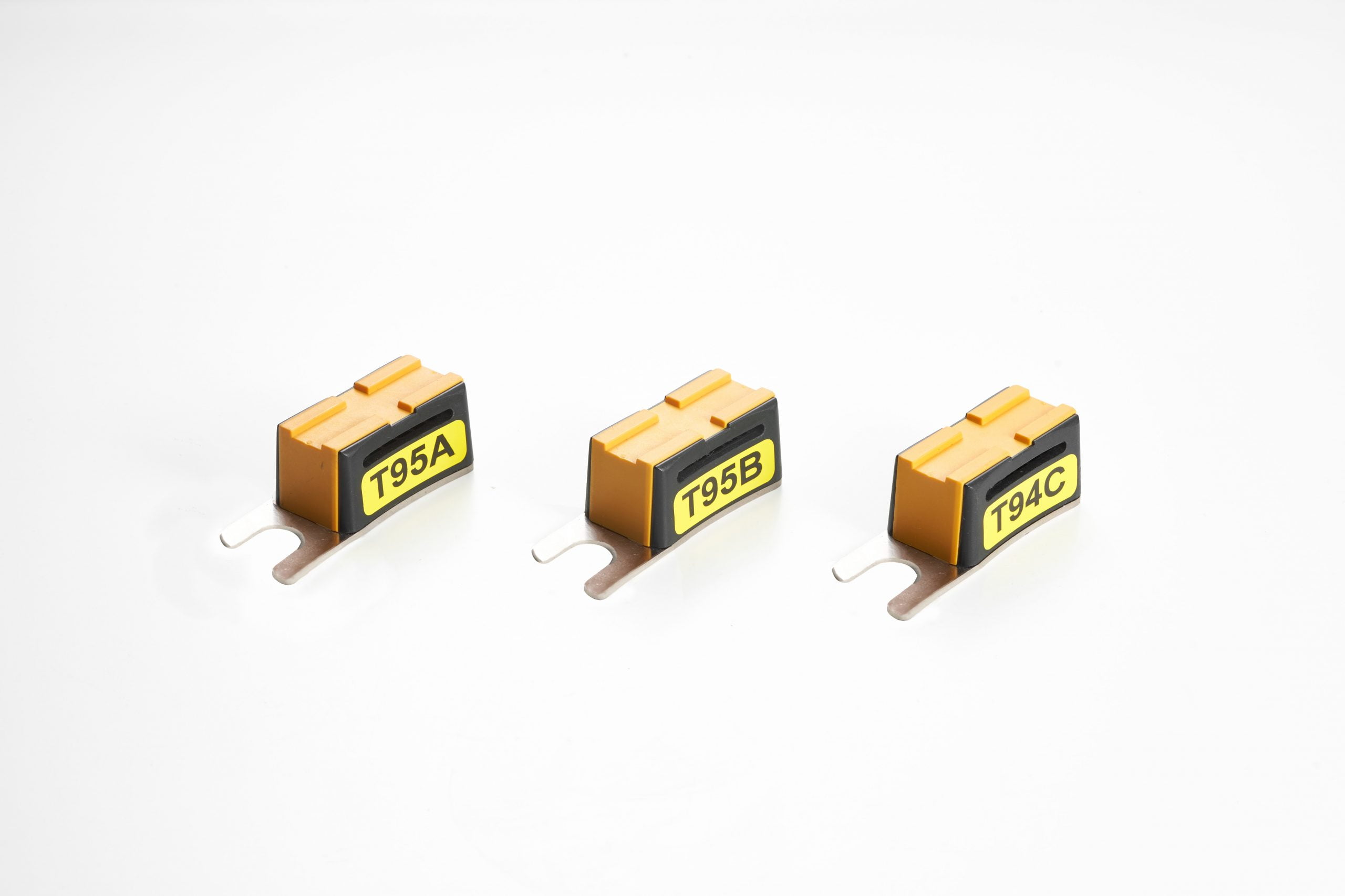
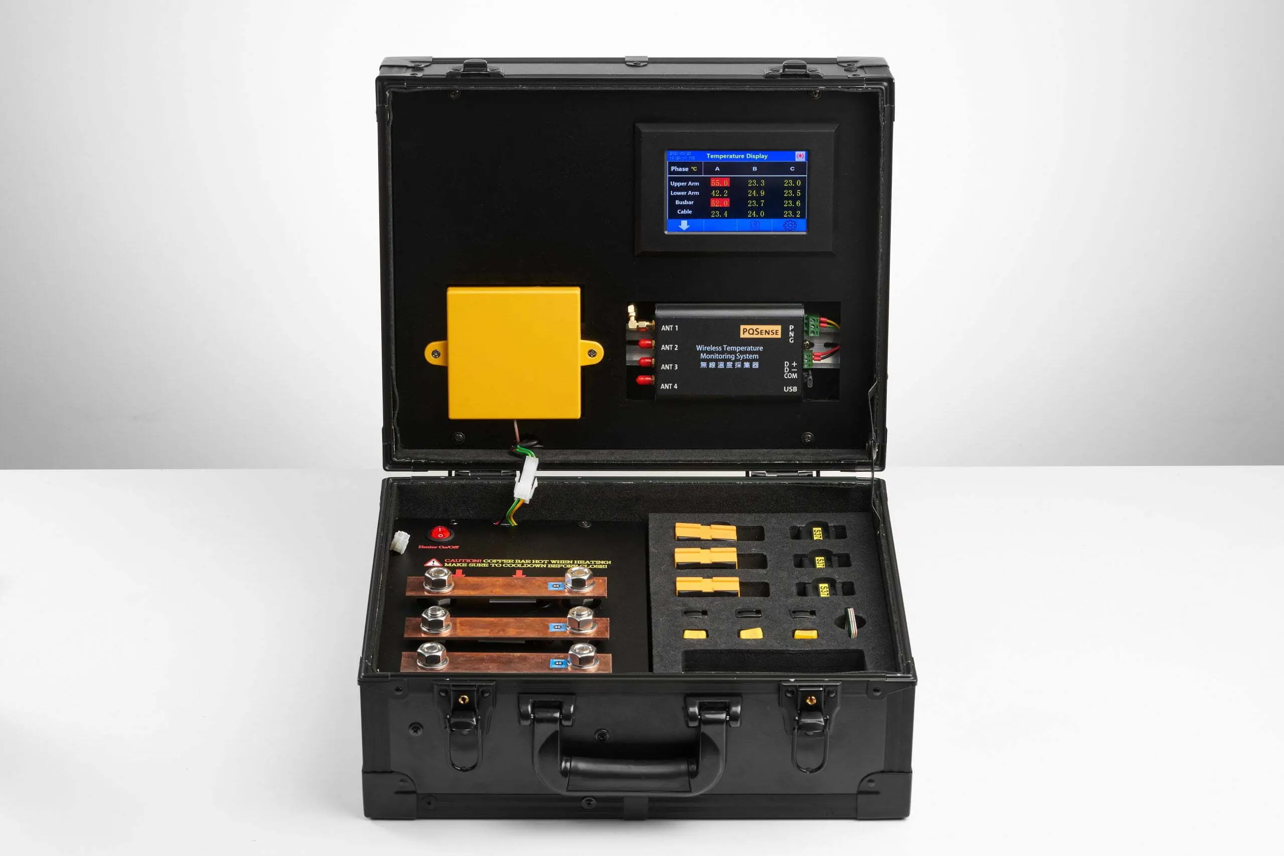
The PQSense wireless temperature monitoring solution uses battery-free passive RFID temperature sensors to measure the temperature directly at selected connections. The sensors receive radio-frequency energy from an antenna, and the reader obtains temperature data through the antenna. Selection requires checking the connection structure, sensor mounting method, and antenna reading configuration together.
Different connections can be matched with appropriate sensors and installation methods:
| Location to be measured | Matching PQSense sensor | What needs to be checked? |
|---|---|---|
| Copper busbar / busbar locations | PQS-SR-01, PQS-SR-05 | Available mounting locations, connection structure, and antenna reading configuration |
| Circuit breaker moving tulip contacts | PQS-SR-02, installed with a dedicated clamp | Contact type and clearance during operation and withdrawal |
| Circuit breaker fixed contacts | PQS-SR-03, installed with a silicone ring | Connection structure, mounting method, and required equipment clearances |
| Ring main unit cable terminations | PQS-SR-11, nut-type sensor | M12 screw-in mounting; confirm compatible cable terminations and antenna reading configuration |
The listed sensors have an official measurement range of −20 to 125°C and a specified accuracy of ±2°C. The PQS-RD-01 fixed reader has an operating temperature range of −20 to 70°C. This describes the reader's operating environment and is a different specification from the sensor measurement range. Selection also requires confirmation of equipment clearances, mounting hardware, and reading conditions.
For the respective roles of power monitoring and electrical connection temperature measurement, see Why Does a Data Center with Power Monitoring Still Need Electrical Connection Temperature Monitoring? . For interpreting temperature changes, see the “Equipment Condition Monitoring” section of Industrial Temperature Monitoring: Heat Sources, Methods and Deployment Decisions.
How Can Monitoring Be Introduced in an Operating Data Center?
How Should the First Equipment Group Be Selected?
Select the first group based on supply criticality. For each measurement point, list its location, sensor model, mounting method, and antenna configuration. Equipment and monitoring solution personnel should then confirm the installation scope and reading feasibility. The measurement-point drawing should map to the actual site equipment, so installation and acceptance use the same list.
How Should the Shutdown Window Be Arranged?
Connection sensors must be installed after the equipment has been de-energized and safety measures completed. The ability to monitor equipment during operation does not mean installation can take place while energized. Confirm the isolation scope, work permits, existing redundancy, and re-energization tests before the site approves a shutdown window. Even dual power feeds do not necessarily allow installation on one feed at a time without interrupting service.
PQSense provides site assessment and shutdown scheduling. The time required should be estimated according to the panel, number of measurement points, antenna and reader installation, isolation, and testing scope—not promised as a single fixed duration per panel.
What Should Be Checked at Handover and Acceptance?
Check each equipment name, sensor ID, and actual installation location. With the panel doors in their normal closed position and under the agreed operating conditions, verify readings, timestamps, and data updates at every measurement point. Then test the agreed alarm functions and data-interruption indication, confirm who takes over when an anomaly occurs, and hand over the measurement-point list, installation records, and operating information.
For an overview of monitoring priorities across data center power distribution equipment, see Which Power Distribution Equipment and Hotspots Should Data Centers and Semiconductor Fabs Monitor? A Complete Temperature Monitoring Guide .
PQSense Solution Specifications at a Glance
| Item | Specification |
|---|---|
| System components | Battery-free RFID temperature sensors, temperature-monitoring antennas, and a fixed temperature reader. |
| Power supply | The sensors are battery-free; the fixed reader requires an external power supply. |
| Suitable measurement points | Suitable busbar joints, circuit breaker contacts, or cable connections, depending on the sensor model. |
| Data interface | The fixed reader supports RS485 / Modbus RTU. Connection to the existing platform and alarm responsibilities must be confirmed during deployment. |
| Sensor measurement range and accuracy | PQS-SR-01 / 02 / 03 / 04 / 05 / 11: −20 to 125°C; accuracy ±2°C. |
| Deployment track record | According to PQSense’s October 2026 deployment reference, more than 16,000 systems have been deployed across more than 300 sites in 17 countries since 2017. About PQSense |
Contact us to discuss monitoring needs at critical data center power distribution locations.