


The First Industry Standard for Continuous Thermal Monitoring
In November 2025, IEEE approved IEEE 2969 — the first formal guide for continuous thermal monitoring of switchgear and motor control centers. For an industry that has relied on periodic infrared inspections for decades, this is a significant shift.
The standard covers equipment rated up to 52 kV and provides guidance on sensor selection, placement, alarm thresholds, and retrofit procedures. It recognizes six monitoring technologies and establishes best practices for implementation.
If your facility currently relies on annual or semi-annual infrared thermography per NFPA 70B, IEEE 2969 provides the framework for moving to continuous monitoring — and a clear technical justification for the investment.
What IEEE 2969 Covers
The guide addresses the complete lifecycle of a thermal monitoring system:
Equipment Scope
- Medium-voltage switchgear — up to 52 kV
- Low-voltage switchgear — including motor control centers (MCCs)
- Key monitoring points — busbar joints, breaker contacts, cable terminations, and incoming/outgoing connections
Six Recognized Monitoring Technologies
IEEE 2969 evaluates six approaches to continuous thermal monitoring, each with distinct trade-offs:
- Infrared (IR) windows — permanent viewing ports for periodic IR thermography without opening panels
- Fiber optic sensors — high accuracy but complex installation and routing
- SAW (Surface Acoustic Wave) sensors — wireless, battery-free, but limited deployment history in switchgear
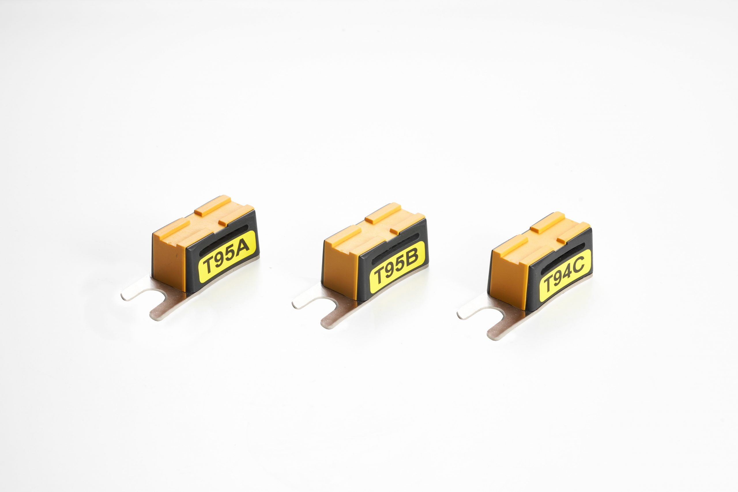
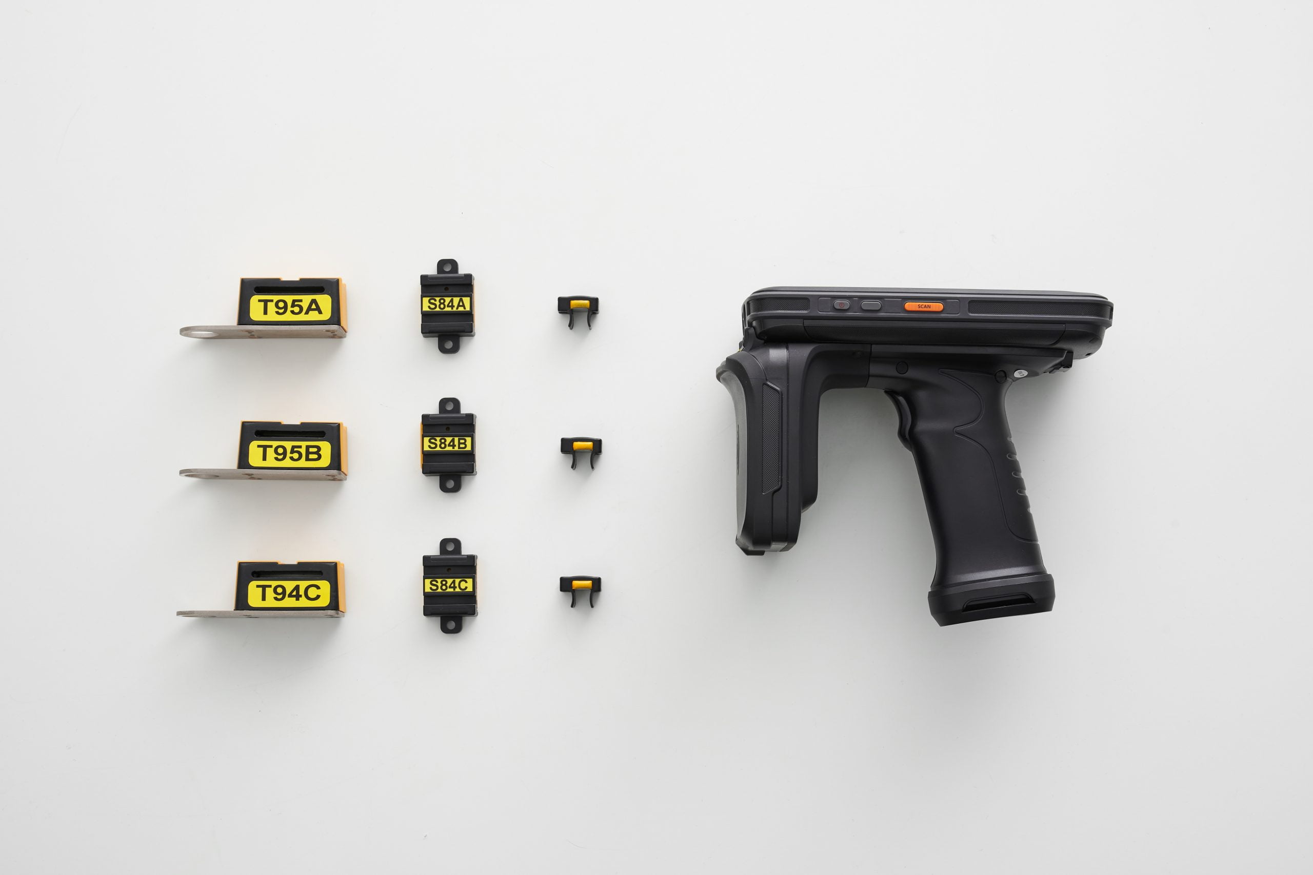
- Passive RFID sensors — wireless, battery-free, digitally addressed, immune to electromagnetic interference
- Active wireless sensors — battery-powered, mature technology, but batteries degrade in high-temperature environments
- Wired sensors (thermocouples/RTDs) — proven accuracy but insulation clearance issues in MV panels
Sensor Placement Recommendations
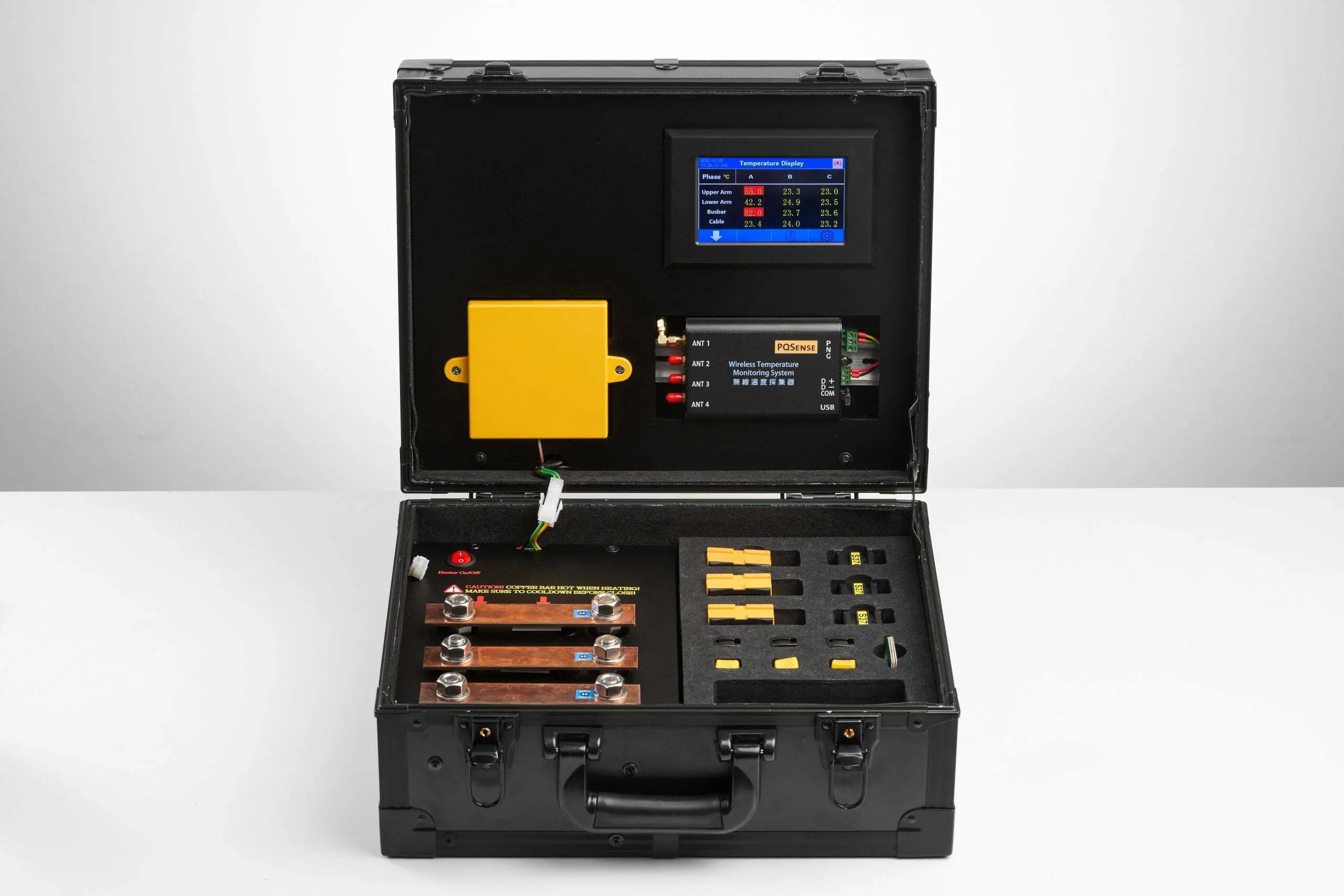
The guide recommends monitoring all three phases at each critical junction point. For a typical switchgear panel, this means:
- Incoming cable terminations (3 sensors — one per phase)
- Busbar joints (3 sensors)
- Outgoing cable terminations or breaker contacts (3 sensors)
Total: 6 to 9 sensors per panel, depending on the configuration and number of connection points.
Alarm Thresholds
IEEE 2969 provides guidance on temperature alarm levels. While specific thresholds depend on the equipment rating and ambient conditions, the standard recommends monitoring:
- Absolute temperature — against the equipment’s rated maximum
- Delta-T between phases — a rising temperature differential between phases at the same junction indicates a developing fault on one phase
- Rate of change — sudden temperature increases warrant immediate attention
Why Passive RFID Stands Out in IEEE 2969
Among the six technologies covered, passive RFID sensors address the constraints that have historically prevented continuous switchgear monitoring:
| Constraint | Passive RFID Solution |
|---|---|
| No power available inside switchgear | Harvests energy from reader’s RF signal — no batteries, no wires |
| High operating temperatures (60°C+) | Rated to +125°C — well above switchgear operating range |
| Metal enclosure blocks signals | Antenna installed inside compartment with sensors — reads through insulation boots, not metal |
| Maintenance access requires outage | Zero maintenance after installation — no battery replacement ever |
| EMI from high-current busbars | Immune to electromagnetic interference — digital addressing prevents cross-talk |
| Retrofit on existing equipment | 30-minute installation per panel during scheduled outage |
From NFPA 70B to IEEE 2969: The Compliance Path
Most facilities today reference NFPA 70B (Recommended Practice for Electrical Equipment Maintenance) for their inspection programs. NFPA 70B recommends periodic infrared thermography — typically annual or semi-annual — based on equipment criticality.
IEEE 2969 doesn’t replace NFPA 70B. Instead, it provides the technical framework for upgrading from periodic inspection to continuous monitoring. The two standards are complementary:
| Aspect | NFPA 70B (Periodic) | IEEE 2969 (Continuous) |
|---|---|---|
| Monitoring approach | Annual/semi-annual IR inspection | 24/7 continuous temperature data |
| Detection window | 1 day per year (0.27% coverage) | 365 days per year (100% coverage) |
| Arc flash exposure | Requires panel access for IR scan | No panel access needed after installation |
| Fault detection | Only if fault is active during inspection | Captures developing faults in real time |
| Data history | Snapshot — no trend data between inspections | Continuous trend data for predictive analysis |
How to Implement IEEE 2969 at Your Facility
Transitioning to continuous thermal monitoring doesn’t require monitoring every panel at once. Most facilities follow a phased approach:
Phase 1: Critical Equipment (Month 1-2)
Start with the highest-risk panels — main incoming feeders, bus-tie breakers, and panels serving critical loads. These are the panels where a failure causes the most damage and downtime.
Phase 2: High-Value Equipment (Month 3-6)
Expand to panels serving production-critical equipment, data center power distribution, and panels with a history of maintenance issues.
Phase 3: Full Coverage (Month 6-12)
Roll out to remaining switchgear panels, motor control centers, and distribution equipment.
Integration
PQSense systems communicate via RS485 / Modbus RTU, integrating directly with existing SCADA, DCS, or cloud platforms. Temperature data flows into your existing monitoring infrastructure — no separate system required.
Getting Started
PQSense has deployed 14,000+ passive RFID temperature monitoring systems worldwide, across semiconductor fabs, power utilities, petrochemical plants, data centers, and rail systems. Our team conducts on-site evaluations to identify the highest-risk panels, recommend sensor configurations, and plan phased deployment aligned with IEEE 2969 guidelines.
